R&D: Noise Reduction in HAMR of Bit-Patterned Media by Optimizing High/Low Tc Bilayer Structure
Different configurations of soft magnetic material and amounts of hard and soft magnetic material tested and discussed.
By Francis Pelletier | December 26, 2017 at 2:28 pmJournal of Applied Physics as published an article written by O. Muthsam, C. Vogler, and D. Suess, University of Vienna, Physics of Functional Materials, Boltzmanngasse 5, 1090 Vienna, Austria.
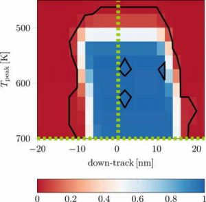
Switching probability phase diagram of a pure FePt like hard magnetic grain.
The contour lines indicate the transition between areas with switching
probability less than 1% (red) and areas with switching probability
higher than 99.2% (blue). The dashed lines mark
the switching probability curves of Fig. 4.

Abstract: “It is assumed that heat-assisted magnetic recording is the recording technique of the future. For pure hard magnetic grains in high density media with an average diameter of 5 nm and a height of 10nm, the switching probability is not sufficiently high for the use in bit-patterned media. Using a bilayer structure with 50% hard magnetic material with low Curie temperature and 50% soft magnetic material with high Curie temperature to obtain more than 99.2% switching probability leads to very large jitter. We propose an optimized material composition to reach a switching probability of Pswitch > 99.2% and simultaneously achieve the narrow transition jitter of pure hard magnetic material. Simulations with a continuous laser spot were performed with the atomistic simulation program VAMPIRE for a single cylindrical recording grain with a diameter of 5nm and a height of 10nm. Different configurations of soft magnetic material and different amounts of hard and soft magnetic material were tested and discussed. Within our analysis, a composition with 20% soft magnetic and 80% hard magnetic material reaches the best results with a switching probability Pswitch > 99.2%, an off-track jitter parameter σoff,80∕20 = 0.46nm and a down-track jitter parameter σdown,80∕20 = 0.49nm.“


 Subscribe to our free daily newsletter
